DIY Smart Appliance: Adding WiFi power control to an integrated amplifier
Previously I was using JBL Bar connected to a TV in my living room. It was controlled with WiFi IR bridge, so whenever my Chromecast or PS4 was in playing state, the Bar was turned on and ready.
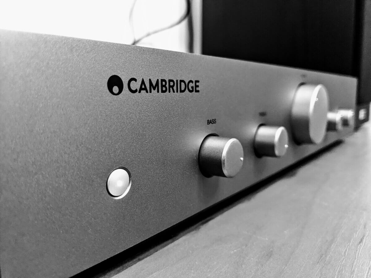
Now I have passive speakers with a simple integrated amplifier, and it can’t be turned on or off without physical interaction. You need to press and release the button on the front panel to toggle amplifier power. So today we will add WiFi power control to Cambridge Audion AXA25 integrated amplifier.
It is not a complex task to simulate button pressing. We just need a relay and a delay. But we also need to detect the amplifier state because there are no differences in turning on and turning off actions. Fortunately, my amplifier has a USB port on the back to power some USB devices. Putting something with an LED indicator in this port helped me to detect that the port is powered only when the amplifier is on. Digital pins of ESP8266 boards are good tools to detect the current presence on a USB port. We will need a 5V power line and a ground line from the port. Here is a pinout of the USB port:

Let’s drow!

Components
- LOLIN (Wemos) D1 mini (wemos.cc)
- 5V Relay Brick by Itead (itead.com)
- AC-DC 220V to 5V Step-Down Mini Power Supply (amazon)
Wemos has a relay shield as well but it can commutate up to 10A current so the electromagnet consumes more power. It is better to use some low-current relay for low-current circuits.
As you can see I’m taking 220V AC power from the amplifier and converting it to 5V DC because we need to power the relay even when the amplifier is off. There is an always-powered low-current circuit that exists in the amplifier, but we can’t use it because of…. well, low current. Connecting a WiFi module and a relay to it will definitely destroy our amplifier.

Firmware
MQTT
If you want to use Arduino IDE to develop and flash the firmware to your Wemos D1 Mini board you’ll need to add an ESP8266 board manager and tools for Arduino. You can do this by performing several simple steps from the official ESP8266 repository. Then you can see the MQTT-based firmware sources I was using before migrating to ESPHome. It could be an example, or you can just use it all.
ESPHome
ESPHome actually makes such projects much easier to implement, improve and support. It also has a very reliable Home Assistant plugin and integration. That is why I moved all my DIY projects to ESPHome and here is a configuration file of my amplifier:
esphome:
  name: amplifier
  platform: ESP8266
  board: d1_mini

wifi:
  ssid: "****"
  password: "**************"

  # Enable fallback hotspot (captive portal) in case wifi connection fails
  ap:
    ssid: "Cambridge AXA25"
    password: "*******"

captive_portal:

# Enable logging
logger:

# Enable Home Assistant API
api:
  password: "******"

ota:
  password: "******"

binary_sensor:
  - platform: gpio
    id: amplifier_power
    internal: true
    pin:
      number: D2
      mode: INPUT_PULLDOWN_16

switch:
  - platform: gpio
    id: relay
    pin: D1
    restore_mode: ALWAYS_OFF
  - platform: template
    name: "Amplifier"
    id: amplifier
    lambda: |-
      if (id(amplifier_power).state) {
        return true;
      } else {
        return false;
      }
    turn_on_action:
      - if:
          condition:
            binary_sensor.is_off: amplifier_power
          then:
          - switch.turn_on: relay
          - delay: 300ms
          - switch.turn_off: relay
    turn_off_action:
      - if:
          condition:
            binary_sensor.is_on: amplifier_power
          then:
          - switch.turn_on: relay
          - delay: 300ms
          - switch.turn_off: relay
That’s it for today. Thanks for reading.