Building WiFi IR remote control for any TV with ESP8266 Wemos D1 mini and ESPHome
Many modern TVs can be controlled not only with an IR remote. Many could be easily integrated with Home Assistant or any other smart home solution. Samsung smart TVs, LG with WebOS… But what if your TV is so dumb it even don’t have WiFi or Bluetooth? Today we’ll add WiFi control to an old and dumb Samsung TV with a little help from ESPHome.
Components and planning
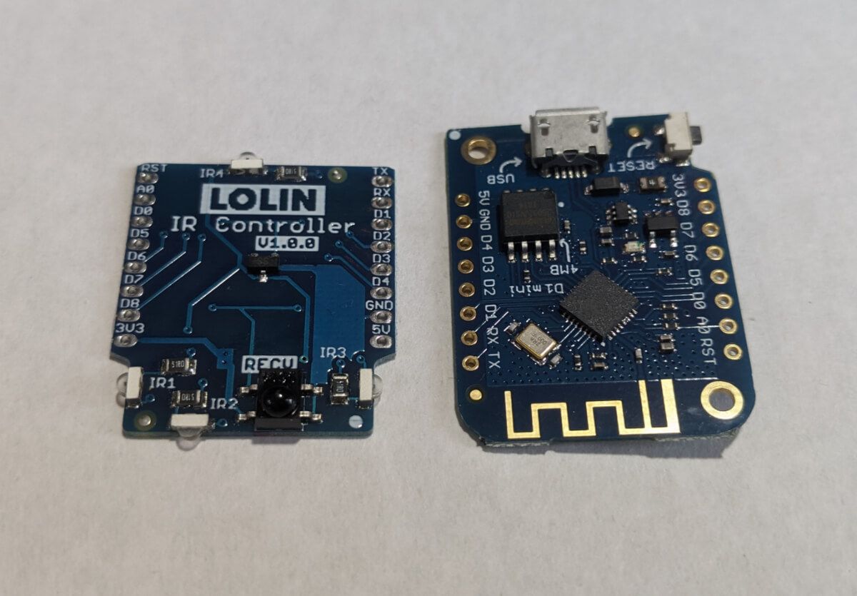
The base of our project would be Wemos D1 mini – an ESP8266-based development board. Actually, it is possible to use any other WiFi development board you’d like, for example, NodeMCU. I choose the D1 mini because of its size and the nice IR shield it has. So the Wemos IR shield is the second part of our future IoT device. The main goal of the project is to receive commands through WiFi and transmit them to the TV using IR LED. So basically we want to build an IR remote where the buttons are replaced with commands through the WiFi.
Also, we will need 5V DC power for our board. We can’t use a factory USB port on our TV because it is not powered when TV is off. I really like to use mini AC-DC converters from Hi-Link in my projects and I really recommend it, but today I’ll need more power because I want to constantly power my Chromecast from the same power source. Because why not. So I found an old power supply that can handle up to 1.2A of current. Should be enough for a WiFi board and Chromecast.

Finally, we will also connect to the factory USB port of our TV. It is the best way to detect TV state (is it on or off currently).
In general, the parts of the project should be connected like this:

Now we will take a look at our TV from the inside.

Build
Power supply
First of all, I removed the housing from my power supply. You don’t need to do this when using a Hi-Link power converter because it has places to solder the wires.

I’ll use a USB port to connect Chromecast to it. Also, I’ll use USB port pins to take power for my WiFi board.

You need to be careful detecting 5V and Ground pins on the USB port. Here is a little help:

From the other side of the power supply board, we have contact plates for AC power. That’s the place where we will solder AC power wires.

Our power supply is ready:

The board

We are ready to build the mainboard now. Wemos D1 mini and its shields come separately from the pin legs. It is a good opportunity to make our device as small as possible.

But first, we need to solder some contacts on the IR shield. It has several IR LEDs as well as several options for a send pin. We will use only one IR LED – IR4, and D3 digital pin for sending IR signal, so we need to solder contact plates on the IR shield like this:

Note that you can use the same board and shield to get IR codes from your TV remote, or build a separate IR receiver. If you will use the same board, you need also to enable receiving LED on the IR shield by soldering the corresponding contact plates. For example, to enable the IR receiver on the D4 pin:


Also, we don’t need such long pin legs so we can shorten it with wire cutters.

And solder the legs finally.
Now the wires. We need 5V and ground from our power supply to be connected to 5V and ground pins of the WiFi board.

Also, we will need the wires to the factory USB port to detect the state of our TV. According to our plan, the 5V from the TV USB port will go to the D2 pin of the Wemos board, and the ground should go to the ground pin.

The firmware
We can make it ourselves. That is what I’ve done in the past. It was a solution that takes BASE64 encoded IR data through MQTT protocol, decodes it, and sends it to the IR led. You can check it on my GitHub. I also had a separate IR receiver to read IR codes from IR remotes and encode them using BASE64. You don’t need all these sources if you are using ESPHome. With ESPHome we will have a simple YAML config for our device:
esphome:
  name: living_room_tv
  platform: ESP8266
  board: d1_mini

wifi:
  ssid: "WiFi"
  password: "************"

  # Enable fallback hotspot (captive portal) in case wifi connection fails
  ap:
    ssid: "Living Room TV"
    password: "************"

captive_portal:

# Enable logging
logger:

# Enable Home Assistant API
api:
  password: "************"
  services:
    - service: volume_up
      then:
        - remote_transmitter.transmit_samsung:
            data: 0xE0E0E01F
    - service: volume_down
      then:
        - remote_transmitter.transmit_samsung:
            data: 0xE0E0D02F
    - service: switch_source
      then:
        - remote_transmitter.transmit_samsung:
            data: 0xE0E0807F
    - service: hdmi1
      then:
        - remote_transmitter.transmit_raw:
            carrier_frequency: 38029
            code: [+4497,-4497,+552,-1657,+552,-1657,+552,-1657,+552,-552,+552,-552,+552,-552,+552,-552,+552,-552,+552,-1657,+552,-1657,+552,-1657,+552,-552,+552,-552,+552,-552,+552,-552,+552,-552,+552,-1657,+552,-552,+552,-552,+552,-1657,+552,-552,+552,-1657,+552,-1657,+552,-1657,+552,-552,+552,-1657,+552,-1657,+552,-552,+552,-1657,+552,-552,+552,-552,+552,-552,+552,-47858]
    - service: hdmi2
      then:
        - remote_transmitter.transmit_raw:
            carrier_frequency: 38029
            code: [+4523,-4497,+552,-1709,+552,-1709,+552,-1709,+552,-579,+552,-579,+552,-579,+552,-579,+552,-579,+552,-1709,+552,-1709,+552,-1709,+552,-579,+552,-579,+552,-579,+552,-579,+552,-579,+552,-579,+552,-1709,+552,-1709,+552,-1709,+552,-1709,+552,-1709,+552,-579,+552,-1709,+552,-1709,+552,-579,+552,-579,+552,-579,+552,-579,+552,-579,+552,-1709,+552,-579,+552,-43993]

ota:
  password: "************"

remote_transmitter:
  pin: D3
  carrier_duty_percent: 50%

binary_sensor:
  - platform: gpio
    id: tv_power
    internal: true
    pin:
      number: D2
      mode: INPUT_PULLDOWN_16

switch:
  - platform: template
    name: "Living Room TV"
    id: living_room_tv
    lambda: |-
      if (id(tv_power).state) {
        return true;
      } else {
        return false;
      }
    turn_on_action:
      - if:
          condition:
            binary_sensor.is_off: tv_power
          then:
          - remote_transmitter.transmit_samsung:
              data: 0xE0E040BF
    turn_off_action:
      - if:
          condition:
            binary_sensor.is_on: tv_power
          then:
           - remote_transmitter.transmit_samsung:
              data: 0xE0E040BF
remote_transmitter is a part where we are declaring our IR transmitter.
binary_sensor is a sensor that will read the voltage from the TV USB port to tell its current state.
switch section is our main functionality. It will be exposed as an entity in Home Assistant and will allow us to control our TV. As you can see from lambda it takes the state from binary_sensor and uses an IR transmitter to send IR “power” command to the TV when turned on or off. It also checks the state of binary_sensor before sending IR command to avoid turning off the TV when it was turned on several times, for example, from automation or service.
data field for remote_transmitter.transmit_samsung can be discovered using a simple ESPHome IR Receiver built with the same Wemos D1 mini and IR shield. You can even do it with the same board we are using for this project as was mentioned before.
I also want to be able to control TV volume and switch input sources through WiFi. So I’ve added a services section in api. All those services would be exposed as esphome services in Home Assistant.
You can see hdmi1 and hdmi2 services have transmit_raw instead of transmit_samsung. This is because I don’t have such buttons on my TV remote to discover the codes so I found the codes in pronto hex format and was able to convert it to raw data with frequency detection using IrScrutinizer.
That’s it. Compile it and flash it with ESPHome Flasher.
TV
Placing the board
Let’s find our TV IR receiver. Usually, it is where the red light is flashing on it. Disassembled my TV more I found it on the bottom edge. We need to put our WiFi board as close as possible to the TV IR receiver pointing our sending IR LED (IR4) in the direction of IR receiver.

While the power from the power supply is not connected yet, we can power the board from a micro USB, power our TV and make the first test.
Warning. You need to be extremely careful when powering on the appliance without its housing! Avoid touching the boards and other internal parts of the appliance because it can lead to appliance damage or your death!

When trying to put the TV housing back on with the WiFi board inside I discovered that I need to make the device even smaller. So I removed IR receiving LED as I have an IR receiver as a separate device. Also, I was forced to solder all wires on the same side of the board.


Now we are ready to use our favorite tool – double-sided adhesive tape, to put the board in its constant living place.
Factory USB port
Here it is on the factory board:

On the other side of this board, we can find the pins where we will solder the wires from the WiFi board – one from D2, and the other from the ground.

Power
Now let’s take a look at the AC power connector on the TV. We can find the pins on the opposite side of the board and solder AC wires from our power supply to it.

Before placing our power supply inside the TV we need to make sure it is isolated from its metal body. I’ve put a layer of plastic under it.

So the overall picture is looking like this:

It is ready! Thanks for reading.